The History of Blueprints:
From 1842 to Modern Engineering

For more than a century, blueprints were one of the most important tools in architecture, engineering and manufacturing. Their distinctive white lines on a deep blue background became a universal symbol of technical precision. But the blueprint did not begin in an architect’s studio or an engineering workshop. It began with a scientific experiment.
1842 — The Birth of the Blueprint
The story of the blueprint begins in 1842 with British scientist and astronomer Sir John Herschel.
Herschel was experimenting with the effects of light on iron-based chemical compounds when he developed a photographic process known as cyanotype.
The process was relatively simple. A surface was coated with light-sensitive chemicals and exposed to sunlight. After exposure and washing, the areas affected by light developed an intense blue colour known as Prussian blue.
Herschel had discovered a practical way of creating permanent photographic images without using silver-based photographic processes.
At first, however, cyanotype had little to do with architecture or engineering.
It was simply a new photographic technique.
1842
Sir John Herschel develops the cyanotype process — the technology that would later make blueprint reproduction possible.

From Photography to Technical Drawings
The potential of Herschel’s invention soon became apparent.
One of the earliest and most famous uses of cyanotype came from botanist and photographer Anna Atkins, who used the process to create detailed images of algae and plants.
Instead of drawing every specimen by hand, Atkins placed the objects directly onto sensitised paper and exposed them to light.
The result was a remarkably detailed white silhouette against a rich blue background.
Her work demonstrated something important: cyanotype could reproduce complex shapes and fine details accurately.
That same principle would eventually make the process extremely useful for copying technical drawings.
The Problem Engineers Needed to Solve
During the 19th century, engineering was becoming increasingly complex.
Railways expanded. Factories grew. Bridges became larger. Machines contained more components. Buildings required increasingly detailed plans.
All of these projects depended on technical drawings.
Engineers and architects created precise drawings showing dimensions, components, materials and construction details.
But there was a major problem:
How do you make accurate copies of a complex technical drawing?
Today, copying a drawing takes seconds.
A digital file can be duplicated infinitely, sent around the world or printed at almost any scale.
In the 19th century, the situation was completely different.
Technical drawings often had to be copied manually or transferred using tracing techniques. This required time and created opportunities for errors.
The cyanotype process offered an elegant solution.
An existing drawing could be reproduced photographically instead of being redrawn.
The Blueprint Enters Engineering
By the 1870s, blueprinting was becoming a practical method for reproducing architectural and engineering drawings.
The principle was remarkably effective.
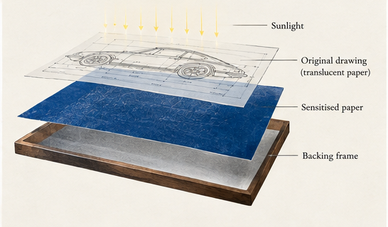
A technical drawing prepared on translucent material could be placed over chemically sensitised paper and exposed to light.
The lines of the original drawing blocked the light.
The exposed areas developed into a deep blue, while the areas beneath the drawing lines remained light.
The result was the image that would become instantly recognisable:
white technical lines on a blue background.

This reproduction method had several important advantages.
It was relatively inexpensive.
It could reproduce intricate details.
And most importantly, multiple copies could be produced from the same original drawing without manually recreating the entire design.
For architects, engineers and manufacturers, this represented a major improvement.
Why Blueprints Changed Engineering
The importance of the blueprint was not simply its distinctive appearance.
Its real value was reproducibility.
A complex machine might contain hundreds or thousands of individual components. A building could involve architects, structural engineers, contractors and numerous workshops.
Everyone needed access to consistent information.
Blueprint reproduction made it easier to distribute the same technical drawing to multiple people.
A drawing created in a design office could be copied and sent to a workshop.
A manufacturer could work from the same specifications as an engineer.
A construction team could refer to copies of the architect’s original plans.
Technical information became easier to reproduce, distribute and preserve.
In an increasingly industrialised world, that mattered enormously.
Blueprints and the Industrial Age
During the late 19th and early 20th centuries, blueprints became closely associated with industrial development.
They were used for architecture, machinery, ships, bridges, railway infrastructure and eventually automobiles and aircraft.
Behind many of the machines that defined the industrial age was a technical drawing.
And behind many of those technical drawings was a method for reproducing them.
The blueprint became part of the infrastructure of engineering itself.
Factories could manufacture components according to documented specifications.
Construction projects could distribute plans between different teams.
Mechanical designs could be recorded and reproduced with remarkable accuracy.
The blue sheet covered with precise white lines became a familiar sight in engineering offices around the world.

Blueprints and the Rise of the Automobile
The arrival of the automobile created another field where technical drawings were essential.
Cars quickly evolved from relatively simple machines into complex combinations of mechanical systems, structural components and carefully designed bodywork.
Engineers needed drawings for engines, chassis, suspension components, gearboxes, body panels and countless smaller parts.
A vehicle could be represented through several technical views:
front, side, rear and top.
These orthographic views allowed engineers to understand the proportions and geometry of an object without the perspective distortion of a conventional illustration.
This visual language is still immediately recognisable today.
And it is one of the reasons historical engineering drawings continue to fascinate automotive enthusiasts.
They allow us to see a car not simply as an object, but as a piece of engineering.
The Blueprint Begins to Change
Traditional cyanotype blueprints were extremely useful, but the technology had limitations.
Producing them required chemically treated paper, exposure to light and washing.
As new reproduction technologies appeared during the 20th century, engineers gradually adopted faster and more convenient methods.
One of the most important successors was the diazo process.
Instead of the familiar white lines on a dark blue background, diazo reproduction could produce coloured lines — often blue — on a light background.
These drawings became known as whiteprints or bluelines.
They were easier to read, annotate and reproduce in many working environments.
The classic blue blueprint slowly began disappearing from everyday engineering offices.
But its name survived.

From Drawing Boards to Computers
The next transformation was much larger.
During the second half of the 20th century, computers began changing the way engineers and architects created technical drawings.
Computer-Aided Design — CAD — allowed drawings to be created digitally.
Lines could be edited without redrawing an entire sheet.
Dimensions could be changed precisely.
Designs could be copied instantly.
Complex components could eventually be represented as three-dimensional digital models.
The advantages were enormous.
By the end of the 20th century, digital design had transformed architecture, manufacturing and engineering.
A technical drawing no longer needed to exist primarily as a physical sheet of paper.
It could exist as data.
The original problem that had made blueprints so revolutionary — how to reproduce a complicated drawing accurately — had essentially disappeared.
A digital file could be duplicated perfectly in an instant.
Why Do We Still Say “Blueprint”?
There is an interesting irony in the history of the blueprint.
The original technology has largely disappeared from professional engineering.
But the word has become more powerful than ever.
Today, blueprint can mean much more than a blue technical drawing.
We use the word to describe a detailed plan:
a blueprint for a building.
a blueprint for a machine.
a blueprint for a business.
a blueprint for the future.
The technology became so closely associated with careful planning and precise design that its name became a metaphor.
Even modern technical illustrations that have never passed through the cyanotype process are often described as blueprint drawings.
The blue paper disappeared.
The idea remained.
From Engineering Document to Visual Culture
Something else happened as traditional blueprints became obsolete.
People began looking at them differently.
Once purely functional documents, old engineering drawings started being appreciated for their visual qualities.
Fine lines.
Mechanical details.
Measurements.
Geometry.
Typography.
Multiple technical views arranged carefully across a page.
What engineers once saw primarily as information could also be seen as design.
Technical drawings began appearing in books, exhibitions, interiors and contemporary artwork.
Automotive drawings were particularly suited to this transformation.
Cars combine engineering with industrial design, making their technical illustrations visually fascinating even when they are removed from their original manufacturing context.
A drawing created to explain how something should be built could now be appreciated simply because of how it looked.
From Blueprint to Contemporary Art
Modern technology has taken this evolution even further.
Today’s artists and designers can work with digital vectors, CAD data, computer-controlled machines and precision drawing tools.
At Plotora, this connection between engineering and art is especially important.
Our automotive artworks are inspired by the visual language of technical drawings — precise lines, multiple views, proportions and engineering details.
But instead of reproducing a 19th-century cyanotype, we use a contemporary process.
Our designs are prepared digitally and then physically drawn using a pen plotter.
A real pen moves across the paper, drawing individual lines with real ink.
In a way, the process brings the history of technical drawing full circle.
The tools have changed.
The purpose has changed.
But the fascination with precision remains.

Nearly Two Centuries of the Blueprint
The history of the blueprint is ultimately the history of how humans communicate complex ideas.
1842: John Herschel develops the cyanotype process.
Late 19th century: blueprint reproduction becomes widely used for engineering and architectural drawings.
Early 20th century: blueprints become an essential part of industrial design, manufacturing and construction.
Mid-20th century: diazo printing and other reproduction technologies begin replacing traditional cyanotypes.
Late 20th century: CAD transforms technical drawing into a predominantly digital process.
Today: the original blueprint is largely historical, but its visual language continues through engineering, design and art.
Almost two centuries after Herschel’s experiments with light-sensitive chemistry, we still immediately understand what those precise lines represent.
An idea.
A design.
Something waiting to be made.
And perhaps that is why the blueprint has survived long after the technology itself became obsolete.