How Blueprints Were Made
Before photocopiers and digital printers, copying a large technical drawing required a very different approach. Instead of scanning the original, engineers used it to control light falling onto a chemically prepared sheet of paper.
The result was an accurate contact copy — the blueprint, produced by the cyanotype process.
Here is how the process worked, step by step.
1. It Started With the Master Drawing
The process began with an original technical drawing created by a draftsman.
But there was an important requirement: the material carrying the drawing needed to transmit light.
For this reason, technical drawings intended for reproduction were commonly prepared or transferred onto translucent supports such as tracing paper or tracing cloth.
The drawing itself contained dark ink lines representing walls, mechanical components, dimensions, annotations and other technical information.
This created a simple optical difference:
the sheet transmitted light, while the dark lines blocked it.
That difference was what made copying possible.

2. A Separate Sheet Was Made Light-Sensitive
The master drawing itself was not turned blue.
A second sheet was used to create the copy.
Paper was coated with a solution containing light-sensitive iron compounds and allowed to dry away from strong light.
At this point there were two separate objects:
the original drawing
and
the sensitised copy paper.
The original could therefore be preserved and used again to make additional copies.

3. The Two Sheets Were Placed Together
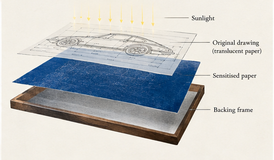
The translucent master drawing was positioned directly on top of the sensitised paper.
They needed to be held very close together.
This is an important detail.
Blueprinting was a contact-printing process.
There was no lens projecting the image onto another surface.
Instead, the original and the copy paper were physically placed against each other.
If there was too much space between them, light could spread underneath the ink lines and make the resulting copy less sharp.
Contact-printing frames were therefore used to press the layers together.
The arrangement looked roughly like this:
LIGHT
MASTER DRAWINGtranslucent sheet + opaque ink lines
SENSITISED PAPER
BACKING / FRAME
Now the copy was ready to be exposed.

4. Light Did the Copying
The assembled frame was exposed to a strong source of light.
Historically, daylight could be used. Later blueprinting equipment provided more controlled artificial exposure.
This is where the actual copying happened.
Light travelled through the relatively transparent areas of the master drawing and reached the sensitised paper underneath.
The dark ink lines behaved differently.
They blocked much of the light.
So the master drawing effectively created a pattern of exposed and protected areas on the sheet below it.
Imagine placing an object on photosensitive paper.
The exposed surroundings react to light.
The area underneath the object does not.
A technical drawing worked according to the same basic principle — only with extremely fine lines.

5. The Master Drawing Was Removed
After sufficient exposure, the frame was opened and the original drawing removed.
Importantly, the original had not been copied by physically transferring its ink.
Nothing moved from one sheet to another.
Instead, the original had simply controlled where light was allowed to reach the sheet beneath it.
This meant the same master drawing could be returned to storage and used again.
Another sensitised sheet could be placed beneath it.
Another exposure could be made.
And another copy produced.
This repeatability was one of the most useful aspects of the process.
6. The Exposed Sheet Was Washed
Exposure alone did not complete the blueprint.
The sheet was then washed in water.
Washing removed soluble, unreacted chemicals from areas that had been protected from light.
The exposed areas remained and developed into the characteristic blue image.
This revealed the drawing clearly:
exposed areas → blue
areas beneath the original ink lines → light
The geometry of the master drawing therefore appeared as light lines against a blue field.
This iron-based reaction is known as cyanotype, and it is why blueprints were blue.

7. The Blueprint Was Dried
After washing, the sheet needed to dry.
Once dry, the copy was ready to use.
The entire reproduction could contain extremely detailed information:
dimensions, annotations, curves, component outlines, section lines and multiple views.
Most importantly, none of those details had to be manually redrawn.
The finished sheet was a direct contact reproduction of the master.

How Could Such Fine Lines Be Copied?
The accuracy came from the fact that the original and copy paper were almost touching.
Consider what happens if you hold your hand close to a wall and shine a light at it.
When your hand is close to the wall, its shadow has relatively sharp edges.
Move your hand farther away and the edges become softer.
The same principle matters in contact printing.
By pressing the technical drawing directly against the sensitised sheet, the process could reproduce surprisingly fine lines.
This made contact between the two surfaces critical to image quality.

What Happened to the Original?
The original drawing remained extremely important.
Blueprints were working copies.
The master could be stored safely while reproduced sheets were sent elsewhere.
If five departments needed the same drawing, five copies could be produced from one master.
If a copy became damaged on a construction site or workshop floor, another could be made.
The master therefore functioned somewhat like a modern digital source file.
It contained the information from which working copies were generated.
How Were Large Drawings Copied?
Engineering drawings could be enormous.
Buildings, ships and complex machinery could require sheets far larger than ordinary documents.
This meant blueprint equipment also had to accommodate large formats.
Commercial copying systems were developed to expose long or wide technical drawings more efficiently.
Instead of an engineer painstakingly reproducing a large sheet by hand, the original could be passed through dedicated reproduction equipment together with sensitised material.
The scale could change.
The fundamental idea did not:
place the original and sensitised material together → expose them to light → process the copy.
Could Blueprints Reproduce Colour?
Traditional blueprint reproduction was primarily suited to line information.
That made it ideal for engineering drawings.
A technical drawing did not need realistic colours, shadows or photographic detail.
What mattered were:
lines,
dimensions,
symbols,
labels,
geometry.
Blueprinting reproduced exactly the type of information engineers needed most.
Why Did the Copy Look Reversed?
A traditional technical drawing generally consisted of dark lines on a light translucent surface.
During contact exposure, those dark lines protected the sensitised paper underneath.
The surrounding areas received light.
The result therefore reversed the visual relationship:
MASTERdark lines
light background
BLUEPRINTlight lines
blue background
This wasn’t a stylistic choice.
It was a direct consequence of the copying process.
One Original, Many Copies
The most important idea behind blueprinting can be reduced to a remarkably simple sequence:
DRAWCreate one accurate master drawing.
CONTACTPlace it against sensitised paper.
EXPOSEUse light to transfer its pattern.
WASHRemove the unreacted chemicals.
DRYReveal the finished copy.
REPEATUse the same master to make another blueprint.
No one needed to redraw the machine.
No one needed to trace every dimension again.
The information contained in the original drawing could be reproduced through light.
And that was the real ingenuity of the blueprint.